
Jdm front conversion issues.Need HELP


Thread Starter
Registered User
Joined: Mar 2012
Posts: 23
Likes: 0
Finishing a front conversion on a 2000 integra .is there an easy connector for adapting the old to new headlight plugs?and the HID headlights on the driver side is hitting the a/c accumilator.what's the fix.do you just manipulate the a/c line rebending it?thanks.
Pops
Joined: Oct 2008
Posts: 2,095
Likes: 0
Since you said EASY...just buy this. New on market. Wireworx Honda JDM Integra "WireTuck-In-A-Box" - WIREWORX
__________________

Jdm b18c R LSD CRX si
TR "Old Skool EF" Member #96
JoKie TuNinG
RANGCRX BUILT TYPE R
StricKlyMT
727-510-6301
Jdm b18c R LSD CRX si
TR "Old Skool EF" Member #96
JoKie TuNinG
RANGCRX BUILT TYPE R
StricKlyMT
727-510-6301
Pops
Joined: Oct 2008
Posts: 2,095
Likes: 0
This appears to be the slightly harder way.
[TABLE="class: tborder, align: center"]
[TR]
[TD="class: alt1"][HR][/HR] Wiring the Lights:
Tools required:
Soldering iron
Solder
Wire stripper
Heat shrink tubing
Cigarette lighter
Small zip ties
Electrical tape
Wire
Third hand tool or another person
1x 0.250" spade connector
1x Automotive Relay and harness
1x inline fuse holder
1x 30A spade fuse
1x ring connector
Foglight switch (USDM, JDM, or generic)
If you are using the USDM turn signal bulbs you will need a file or a Dremel.
For OEM JDM HIDs you will need an additional:
2x Automotive relay and harness
2x inline fuse holder
2x 30A spade fuse
2x ring connector
You should have general knowledge about running wires and soldering before you begin. You should also have knowledge of how relays work. Always solder all connections for the longest-lasting connection; do not use quick connects, butt connectors, spade connectors, or the "twist and tape" method. Use heat shrink tubing after soldering to protect the connection. Never leave electrical connections exposed to the elements. Always use a fuse.
 [TABLE="class: ncode_imageresizer_warning2"]
[TR]
[TD="class: td2, width: 100%, align: right"][/TD]
[TD="class: td1"][/TD]
[/TR]
[/TABLE]
JDM front wiring diagram
1. Disconnect the negative battery terminal.
2. Unplug the JDM headlight wiring harness from the headlight assembly.
3. Remove the JDM turn signal bulbs and sockets from the headlights.
Now you have a choice to make. You can either have USDM-style turn signals (the turn signal is dim when you have your parking lights on and flashes brighter when you activate your turn signal. The purpose of this is so that if one of your headlights goes out, other cars can still distinguish the outline of your car at night) or JDM-style turn signals (the turn signal is on only when you activate your turn signal. This configuration is technically illegal in the US, but so is having a JDM front since the headlights aren't DOT certified anyway)
For USDM-style turn signals:
4. Take the existing turn signal bulb and socket from your USDM front and file down the tabs of the socket so that they fit properly in the holes of the JDM headlight.
For JDM-style turn signals:
4a. Cut the three wires coming from the USDM turn signal bulb and socket.
4b. Take the JDM turn signal bulb and socket. Solder the green wire and the black wire from the JDM socket to the green wire and the black wire, respectively, that you just cut. You may need to extend the wires.
Similarly, you must make a choice about how you want your side markers to function. You can either have them on constantly along with your parking lights, or you can have them blink with your turn signals.
For constant-on sidemarkers:
5. Solder the red wire from the USDM turn signal to the red wire from the sidemarkers. Solder the black wire from the sidemarkers to any ground point or any black wire.
For flashing-with-turn-signal sidemarkers:
5. Solder the green wire from the USDM turn signal to the red wire from the sidemarkers. Solder the black wire from the sidemarkers to any ground point or any black wire.
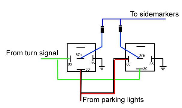
Update: You can also have the sidemarkers on with your parking lights AND blink with your turn signals.
To do this, you will need:
4x Automotive relay and harness
4x diode (1N4001 or similar)
See the diagram below for how to wire the sidemarkers in this fashion. Wire the other end of the sidemarkers to ground. (You have to do this for each side of the car). There is a way to do it without diodes too, I will put that up shortly.
 [TABLE="class: ncode_imageresizer_warning2"]
[TR]
[TD="class: td2, width: 100%, align: right"][/TD]
[/TR]
[/TABLE]
Now you may wire the headlights.
For non-HID headlights:
6. Remove the headlight bulb and socket from the JDM headlight and insert your USDM bulb and socket (they should be the same, no modification necessary). You now have a spare set of headlight bulbs.
For OEM JDM HID headlights:
6a. Cut the wires attached to your USDM headlight bulb socket.
6b. Solder the red wire you just cut to pin 86 of an automotive relay.
6c. Solder the black wire you just cut to pin 85 of the relay.
6d. Solder pin 30 of the relay to an in-line fuse holder and attach the other end of the fuse holder directly to the positive batter terminal via a ring connector. Put a 30A fuse in the in-line fuse holder.
6e. Solder pin 87 of the relay to the red or white wire leading into the HID ballast. Alternatively, you can wire pin 87 to the bottom center position of the headlight wiring harness.
6f. Repeat for the other headlight.
Finally, we can do the fog, high beam, and parking/city lights.
Parking/city lights:
7. Take the red wire from the USDM turn signal mentioned in step 4 and solder/splice it to the red/black wire coming out of the JDM headlight harness.
Fog lights:
See the G3 Factory Foglight Wiring article for illustrations.
8. Solder the two yellow/red wires from the JDM headlight harnesses together.
9. Solder the yellow/red wires to pin 87 of an automotive relay.
10. Solder pin 30 of the relay to an inline fuse holder. Insert a 30A fuse into the inline fuse holder.
11. Connect the other end of the fuse holder directly to the battery via a ring connector (or some other suitable method).
12. Connect pin 85 of the relay to any ground point or wire.
13. Connect pin 86 of the relay to the OEM foglight wire plug. This plug is located on the driver's side near the headlight wiring and is a brown 1-pin receptacle with a blue/red wire. You can connect to the pin using a 0.25" female spade connector.
14. Find the other end of the OEM foglight wire in the passenger compartment, in the driver footwell. Connect a wire to this plug with a 0.25" spade connector and run that wire to the normally-closed switch of your choice.
15. Connect the other end of the switch to a 12V source, preferably one that is only on when the key is in the ignition so you don't accidentally leave your foglights on when you park and drain the battery. You can use the accessory plug from the fusebox to accomplish this.
15b. If you are using the JDM or USDM foglight switch, you need to connect the black wire to ground.
High beams:
16. Solder the red/green (passenger side) and the red/blue (driver side) wires from the JDM headlight harness to the same-colored USDM wires on the car.
17. Double-check all connections and make sure you haven't shorted any of them. Make sure the fog light connection and the OEM JDM HID connections, if you have them, are fused.
18. Re-connect the negative battery terminal and test the lights.
[/TD]
[/TR]
[TR]
[TD="class: alt2"]
[/TD]
[TD="class: alt1, align: right"]
[/TD]
[/TR]
[/TABLE]
[TABLE="class: tborder, align: center"]
[TR]
[TD="class: alt1"][HR][/HR] Wiring the Lights:
Tools required:
Soldering iron
Solder
Wire stripper
Heat shrink tubing
Cigarette lighter
Small zip ties
Electrical tape
Wire
Third hand tool or another person
1x 0.250" spade connector
1x Automotive Relay and harness
1x inline fuse holder
1x 30A spade fuse
1x ring connector
Foglight switch (USDM, JDM, or generic)
If you are using the USDM turn signal bulbs you will need a file or a Dremel.
For OEM JDM HIDs you will need an additional:
2x Automotive relay and harness
2x inline fuse holder
2x 30A spade fuse
2x ring connector
You should have general knowledge about running wires and soldering before you begin. You should also have knowledge of how relays work. Always solder all connections for the longest-lasting connection; do not use quick connects, butt connectors, spade connectors, or the "twist and tape" method. Use heat shrink tubing after soldering to protect the connection. Never leave electrical connections exposed to the elements. Always use a fuse.
 [TABLE="class: ncode_imageresizer_warning2"]
[TR]
[TD="class: td2, width: 100%, align: right"][/TD]
[TD="class: td1"][/TD]
[/TR]
[/TABLE]
JDM front wiring diagram
1. Disconnect the negative battery terminal.
2. Unplug the JDM headlight wiring harness from the headlight assembly.
3. Remove the JDM turn signal bulbs and sockets from the headlights.
Now you have a choice to make. You can either have USDM-style turn signals (the turn signal is dim when you have your parking lights on and flashes brighter when you activate your turn signal. The purpose of this is so that if one of your headlights goes out, other cars can still distinguish the outline of your car at night) or JDM-style turn signals (the turn signal is on only when you activate your turn signal. This configuration is technically illegal in the US, but so is having a JDM front since the headlights aren't DOT certified anyway)
For USDM-style turn signals:
4. Take the existing turn signal bulb and socket from your USDM front and file down the tabs of the socket so that they fit properly in the holes of the JDM headlight.
For JDM-style turn signals:
4a. Cut the three wires coming from the USDM turn signal bulb and socket.
4b. Take the JDM turn signal bulb and socket. Solder the green wire and the black wire from the JDM socket to the green wire and the black wire, respectively, that you just cut. You may need to extend the wires.
Similarly, you must make a choice about how you want your side markers to function. You can either have them on constantly along with your parking lights, or you can have them blink with your turn signals.
For constant-on sidemarkers:
5. Solder the red wire from the USDM turn signal to the red wire from the sidemarkers. Solder the black wire from the sidemarkers to any ground point or any black wire.
For flashing-with-turn-signal sidemarkers:
5. Solder the green wire from the USDM turn signal to the red wire from the sidemarkers. Solder the black wire from the sidemarkers to any ground point or any black wire.
Update: You can also have the sidemarkers on with your parking lights AND blink with your turn signals.
To do this, you will need:
4x Automotive relay and harness
4x diode (1N4001 or similar)
See the diagram below for how to wire the sidemarkers in this fashion. Wire the other end of the sidemarkers to ground. (You have to do this for each side of the car). There is a way to do it without diodes too, I will put that up shortly.
[TABLE="class: ncode_imageresizer_warning2"][TR]
[TD="class: td2, width: 100%, align: right"][/TD]
[/TR]
[/TABLE]
Now you may wire the headlights.
For non-HID headlights:
6. Remove the headlight bulb and socket from the JDM headlight and insert your USDM bulb and socket (they should be the same, no modification necessary). You now have a spare set of headlight bulbs.
For OEM JDM HID headlights:
6a. Cut the wires attached to your USDM headlight bulb socket.
6b. Solder the red wire you just cut to pin 86 of an automotive relay.
6c. Solder the black wire you just cut to pin 85 of the relay.
6d. Solder pin 30 of the relay to an in-line fuse holder and attach the other end of the fuse holder directly to the positive batter terminal via a ring connector. Put a 30A fuse in the in-line fuse holder.
6e. Solder pin 87 of the relay to the red or white wire leading into the HID ballast. Alternatively, you can wire pin 87 to the bottom center position of the headlight wiring harness.
6f. Repeat for the other headlight.
Finally, we can do the fog, high beam, and parking/city lights.
Parking/city lights:
7. Take the red wire from the USDM turn signal mentioned in step 4 and solder/splice it to the red/black wire coming out of the JDM headlight harness.
Fog lights:
See the G3 Factory Foglight Wiring article for illustrations.
8. Solder the two yellow/red wires from the JDM headlight harnesses together.
9. Solder the yellow/red wires to pin 87 of an automotive relay.
10. Solder pin 30 of the relay to an inline fuse holder. Insert a 30A fuse into the inline fuse holder.
11. Connect the other end of the fuse holder directly to the battery via a ring connector (or some other suitable method).
12. Connect pin 85 of the relay to any ground point or wire.
13. Connect pin 86 of the relay to the OEM foglight wire plug. This plug is located on the driver's side near the headlight wiring and is a brown 1-pin receptacle with a blue/red wire. You can connect to the pin using a 0.25" female spade connector.
14. Find the other end of the OEM foglight wire in the passenger compartment, in the driver footwell. Connect a wire to this plug with a 0.25" spade connector and run that wire to the normally-closed switch of your choice.
15. Connect the other end of the switch to a 12V source, preferably one that is only on when the key is in the ignition so you don't accidentally leave your foglights on when you park and drain the battery. You can use the accessory plug from the fusebox to accomplish this.
15b. If you are using the JDM or USDM foglight switch, you need to connect the black wire to ground.
High beams:
16. Solder the red/green (passenger side) and the red/blue (driver side) wires from the JDM headlight harness to the same-colored USDM wires on the car.
17. Double-check all connections and make sure you haven't shorted any of them. Make sure the fog light connection and the OEM JDM HID connections, if you have them, are fused.
18. Re-connect the negative battery terminal and test the lights.
[/TD]
[/TR]
[TR]
[TD="class: alt2"]
[/TD]
[TD="class: alt1, align: right"]
[/TD]
[/TR]
[/TABLE]
__________________
Jdm b18c R LSD CRX si
TR "Old Skool EF" Member #96
JoKie TuNinG
RANGCRX BUILT TYPE R
StricKlyMT
727-510-6301
Jdm b18c R LSD CRX si
TR "Old Skool EF" Member #96
JoKie TuNinG
RANGCRX BUILT TYPE R
StricKlyMT
727-510-6301

Thread
Thread Starter
Forum
Replies
Last Post
cagedeyecam
For Sale/WTB Nissan
2
Jun 21, 2011 09:08 AM
like50wambats
For Sale/WTB Honda & Acura
0
Apr 17, 2011 10:09 AM
tegy92
For Sale/WTB Honda & Acura
2
Sep 21, 2008 11:59 AM


