
FAQ: About Chassis and Suspension (Reading Required)

Thread Starter
legend behind the cowl
Joined: May 2006
Posts: 1,840
Likes: 0
I am beginning to realize the lack of good information available in respect to this forum. In an attempt to bring the education level of this forum to the level it should be. I am going to over the next couple weeks the following.
Basic Theory:
Why do I even Need suspension
Diffrent types of suspension (What do I have?)
Under/Oversteer (I can make my car do that?)
Sprung Vs. Unsprung Weight (lighter is better)
Slip vs. Grip angle (when turning the wheel is bad)
Tires (tires are a spring? and the "Gription theory")
Basic Math (I'm no engineer, how do I figure this out)
Tyre-road friction and tyre slip (tyre loading as requested)
Centrifugal Force (the imaginary cornering force)
Traction Circle (spending money in the RIGHT places)
Center of Gravity, (why lower is not ALWAYS faster)
Weight transfer (the springrate and swaybar guide)
Dampers (Shocks, struts, what do these things do, and how)
Suspension Travel (the rally diaries)
Putting power down (FWD, AWD, RWD Vs. Jet power)
Allignment:
Kingpin Angles (steering axis inclination)
Toe In or out (Of the swimming pool?)
Roll Centers (camber gain under compression)
Castor (Scrub Radius)
Squat and Dive (and how they change the dynamics)
Spring Pre-load (I may not need it, do I want it?)
Stock vs. mild street vs. racing (my car stinks on ice)
Using this Knowledge on track:
Racing Line (how can I corner faster)
Horsepower (how a Miata "can" beat a corvette)
Race Braking theory (Threshold braking vs. ABS)
Tuning Dampers and Spring Rate (Spotting BS from fact)
I will update this post with the information as I get to it, the following thread will be for questions and answers so I can update this post and then make a proper FAQ out of it. if we can keep the questions to the current topic I'd appreciate it.. when we are done we should have a decent FAQ
THIS IS NOT A THREAD FOR VENDORS TO SELL THEIR SERVICES. DON'T EVEN THINK ABOUT IT!
Last edited by treekiller; Aug 18, 2008 at 08:13 PM.
Thread Starter
legend behind the cowl
Joined: May 2006
Posts: 1,840
Likes: 0
Well... you don't NEED suspension, Lets look at a go-kart. one of the best handling vehicles in the world... Their suspension is fixed, yes there is still alignment, however as we will discuss later in this article, A go kart tyre and wheel is specifically designed to act as the only vertical motion between the chassis and the ground. and the tyre acts as a Spring AND a shock, but like I said we will touch on that later. so the spring rate on a go kart is infinity, there is a small bit of chassis flex, but for our purposes we will assume ZERO spring rate or a rate of infinity. (maybe there is more to suspension thing then I assumed)
Now if we all drove around on perfectly flat smooth roads, we could get away without suspensions, Bicycles made due for centuries with out suspensions but recently it's hard to buy one without. so I don't NEED a suspension? RIGHT But I want one? YES, if you want to travel at any speed.
so since we don't live in a world with perfectly flat smooth roads we need to compromise, our tires need to travel up and down, they need to follow the pavement, allow us to traverse curbs, handle the occasional pothole at 75mph without spearing off into the tree line, but what else does my suspension do?
1: It carries the weight of the car, and allows changes in weight, and cargo.
2: It keeps the wheels perpendicular to the road, regardless of what the car is doing
3: It allows us to accelerate and brake with great force.
4: it handles large torque loads without twisting the wheels off the car
5: It handles large lateral loads, cornering forces, (much more when we are done)
Last edited by treekiller; Mar 14, 2008 at 10:20 PM.
Thread Starter
legend behind the cowl
Joined: May 2006
Posts: 1,840
Likes: 0
(content and pictures used with thanks to carbibles.com)
There are several diffrent types of suspension design, the earliest vehicle suspensions are thousands of years old found on OX carts (wagons) and chariots. now they were basically a solid axle between 2 wheels and some rudimentary form of spring. there was no damper other then the friction within the spring, and cars used friction dampers well into the 1930's. so our modern suspension design is a very new science. (in the grand scheme of things)
What are the major suspension types? since we know no cars we drive are using dead solid axles there must be something diffrent. and there are several variants More then I can list so I am going to focus on the "TOP 9"
1. Live Axle + 4 Link Live axle
2. De Deion
3. McPherson and Chapman Strut
4. Double Wishbone
5. Multi Link
6. trailing Arm + Semi Trailing Arm.
7. Transverse Leaf Spring
8. Beam axle (more often twist beam)
9. Ford Control Blade
Solid-axle, leaf-spring

This system was favoured by the Americans for years because it was dead simple and cheap to build. The ride quality is decidedly questionable though. The drive axle is clamped to the leaf springs and the shock absorbers normally bolt directly to the axle. The ends of the leaf springs are attached directly to the chassis, as are the tops of the shock absorbers. Simple, not particularly elegant, but cheap. The main drawback with this arrangement is the lack of lateral location for the axle, meaning it has a lot of side-to-side slop in it.
Solid-axle, coil-spring

This is a variation and update on the system described above. The basic idea is the same, but the leaf springs have been removed in favour of either 'coil-over-oil' spring and shock combos, or as shown here, separate coil springs and shock absorbers. Because the leaf springs have been removed, the axle now needs to have lateral support from a pair control arms. The front ends of these are attached to the chassis, the rear ends to the axle. The variation shown here is more compact than the coil-over-oil type, and it means you can have smaller or shorter springs. This in turn allows the system to fit in a smaller area under the car.
4-Bar


4-bar suspension can be used on the front and rear of vehicles - I've chosen to show it in the "rear" section of this page because that's where it's normally found. 4-bar suspension comes in two varieties. Triangulated, shown on the right here, and parallel, shown on the left.
The parallel design operates on the principal of a "constant motion parallelogram". The design of the 4-bar is such that the rear end housing is always perpendicular to the ground, and the pinion angle never changes. This, combined with the lateral stability of the Panhard Bar, does an excellent job of locating the rear end and keeping it in proper alignment. If you were to compare this suspension system on a truck with a 4-link or ladder-bar setup, you'd notice that the rear frame "kick up" of the 4-bar setup is far less severe. This, combined with the relatively compact installation design means that it's ideal for cars and trucks where space is at a premium. You'll find this setup on a lot of street rods and American style classic hot rods.
The triangulated design operates on the same principle, but the top two bars are skewed inwards and joined to the rear end housing much closer to the centre. This eliminates the need for the separate panhard bar, which in turn means the whole setup is even more compact.
Derivatives of the 4-Bar system
There are many variations on the 4-bar systems I've illustrated above. For example, if the four angled bars go from the axle outboard to the chassis near the centreline, this is called a "Satchell link". (Satchell is a US designer, who used the above linkage on some of Paul Newmans Datsun road racers some years back.) It has certain advantages over the above examples. Both of the these angled linkages can be reversed to have the angled links below the axle and the parallel links above. The roll centre will be lowered with the angled bars under the axle, a function which is difficult to accomplish without this design. The other variation on the "four bars" not shown are the Watts and Jacobs bar linkages to replace the Panhard rod for lateral positioning. Another linkage is the two parallel bars above the axle and a triangulated link underneath - a design you will find on the Lotus 7 - where the lower link has its base on the chassis and the apex under the differential. Then there is the Mallock Woblink, which could be described as half way between a Jacobs ladder and a Watts link, and makes it possible to place the rear roll centre quite low without sacrificing ground clearance.
Watts links are pretty popular with the hydraulic lowrider/truck bed dancer types. The Jacobs ladder is used almost exclusively on US midget and sprintcar dirt track rear ends. The Mallock Woblink is used mostly on the Mallock U2 Clubman cars in Great Britain.
de Dion suspension, or the de Dion tube
de Dion suspension, or the de Dion tube

The de Dion tube - not part of the London underground, but rather a semi-independent rear suspension system designed to combat the twin evils of unsprung weight and poor ride quality in live axle systems. de Dion suspension is a weird bastardisation of live-axle solid-beam suspension and fully independent trailing-arm suspension. It's neither one, but at the same time it's both. Weird! With this system, the wheels are interconnected by a de Dion Tube, which is essentially a laterally-telescoping part of the suspension designed to allow the wheel track to vary during suspension movement. This is necessary because the wheels are always kept parallel to each other, and thus perpendicular to the road surface regardless of what the car body is doing. This setup means that when the wheels rebound, there is also no camber change which is great for traction, and that's the first advantage of a de Dion Tube. The second advantage is that it contributes to reduced unsprung weight in the vehicle because the transfer case / differential is attached to the chassis of the car rather than the suspension itself.
Naturally, the advantages are equalled by disadvantages, and in the case of de Dion systems, the disadvantages would seem to win out. First off, it needs two CV joints per axle instead of only one. That adds complexity and weight. Well one of the advantages of not having the differential as part of the suspension is a reduction in weight, so adding more weight back into the system to compensate for the design is a definite distadvantage. Second, the brakes are mounted inboard with the calipers attached to the transfer case, which means to change a brake disc, you need to dismantle the entire suspension system to get the driveshaft out. (Working on the brake calipers is no walk in the park either.) Finally, de Dion units can be used with a leaf-spring or coil-spring arrangement. With coil spring (as shown here) it needs extra lateral location links, such as a panhard rod, wishbones or trailing links. Again - more weight and complexity.
de Dion suspension was used mostly used from the mid 60's to the late 70's and could be found on some Rovers, the Alfa Romeo GTV6, one or two Lancias a smattering of exotic racing cars and budget sports cars or coupes.
More recently deDion suspension has had somewhat of a renaissance in the specialist sports car and kit car market such as those from Caterham, Westfield and Dax. These all uniformly now use outboard brake setups for ease-of-use, and a non-telescoping tube, usually with trailing links and an A-bar for lateral location (rather than a Watts linkage or Panhard rod.) Whilst a properly setup independent suspension system will always win hands-down on poorly maintained roads, when you get on to the track, the advantage is not so clear cut and a well set up deDion system can often match it turn-for-turn now, espeically for flyweight cars.
MacPherson Strut or Chapman strut

This is currently, without doubt, the most widely used front suspension system in cars of European origin. It is simplicity itself. The system basically comprises of a strut-type spring and shock absorber combo, which pivots on a ball joint on the single, lower arm. At the top end there is a needle roller bearing, which allows the assembly to pivot as a single solid unit. In the picture here, you can't see the shock absorber because it is encased in the black gaiter inside the spring.
The steering gear is either connected directly to the lower shock absorber housing, or to an arm from the front or back of the spindle (in this case). When you steer, it physically twists the strut and shock absorber housing (and consequently the spring) to turn the wheel. Simple. The spring is seated in a special plate at the top of the assembly which allows this twisting to take place. If the spring or this plate are worn, you'll get a loud 'clonk' on full lock as the spring frees up and jumps into place. This is sometimes confused for CV joint knock.
Double wishbone


Type 1 Type 2
Coil Spring type 1
This is a type of double-A or double wishbone suspension. The wheel spindles are supported by an upper and lower 'A' shaped arm. In this type, the lower arm carries most of the load. If you look head-on at this type of system, what you'll find is that it's a very parallelogram system that allows the spindles to travel vertically up and down. When they do this, they also have a slight side-to-side motion caused by the arc that the wishbones describe around their pivot points. This side-to-side motion is known as scrub. Unless the links are infinitely long the scrub motion is always present. There are two other types of motion of the wheel relative to the body when the suspension articulates. The first and most important is a toe angle (steer angle). The second and least important, but the one which produces most pub talk is the camber angle, or lean angle. Steer and camber are the ones which wear tyres.
Coil Spring type 2 This is also a type of double-A arm suspension although the lower arm in these systems can sometimes be replaced with a single solid arm (as in my picture). The only real difference between this and the previous system mentioned above is that the spring/shock combo is moved from between the arms to above the upper arm. This transfers the load-bearing capability of the suspension almost entirely to the upper arm and the spring mounts. The lower arm in this instance becomes a control arm. This particular type of system isn't so popular in cars as it takes up a lot room.
Multi-link suspension

This is the latest incarnation of the double wishbone system described above. It's currently being used in the Audi A8 and A4 amongst other cars. The basic principle of it is the same, but instead of solid upper and lower wishbones, each 'arm' of the wishbone is a separate item. These are joined at the top and bottom of the spindle thus forming the wishbone shape. The super-weird thing about this is that as the spindle turns for steering, it alters the geometry of the suspension by torquing all four suspension arms. They have complex pivot systems designed to allow this to happen.
Car manufacturers claim that this system gives even better road-holding properties, because all the various joints make the suspension almost infinitely adjustable. There are a lot of variations on this theme appearing at the moment, with huge differences in the numbers and complexities of joints, numbers of arms, positioning of the parts etc. but they are all fundamentally the same. Note that in this system the spring (red) is separate from the shock absorber (yellow).
Trailing-arm suspension

The trailing arm system is literally that - a shaped suspension arm is joined at the front to the chassis, allowing the rear to swing up and down. Pairs of these become twin-trailing-arm systems and work on exactly the same principle as the double wishbones in the systems described above. The difference is that instead of the arms sticking out from the side of the chassis, they travel back parallel to it. This is an older system not used so much any more because of the space it takes up, but it doesn't suffer from the side-to-side scrubbing problem of double wishbone systems. If you want to know what I mean, find a VW beetle and stick your head in the front wheel arch - that's a double-trailing-arm suspension setup. Simple.
Transverse leaf-spring

This system is a bit odd in that it combines independent double wishbone suspension with a leaf spring like you'd normally find on the rear suspension. Famously used on the Corvette, it involves one leaf spring mounted across the vehicle, connected at each end to the lower wishbone. The centre of the spring is connected to the front subframe in the middle of the car. There are still two shock absorbers, mounted one to each side on the lower wishbones. Chevy insist that this is the best thing since sliced bread for a suspension system but there are plenty of other experts, manufacturers and race drivers who think it's junk. It's never been clear if this was a performance and design decision or a cost issue, but this type of system is very rare.
 Historically, Triumph used transverse leaf spring suspension on their small chassis cars (Herald, Vitesse, Spitfire & GT6). In the good old British school of thought, they did this because it was cheap. The spring was bolted to the differential, rather than the chassis, and under (very) hard cornering you got jacking and tuck-under. If you got this whilst driving and panicked enough to let off the gas, or worse, step on the brake, you got massive over-steer, and pirouetted off into the nearest tree. There were plenty of complaints about this suspension system in the late 60's, so Triumph changed to a 'swing spring' system on some cars (no longer bolted to the diff), and what they called 'rotoflex' on the GT6. Again from the good old British school of thought, the replacement system was unnecessarily complicated and allegedly very fragile.
Beam Axle

This system is used in front wheel drive cars, where the rear axle isn't driven. (hence it's full description as a "dead beam"). Again, it is a relatively simple system. The beam runs across under the car with the wheels attached to either end of it. Spring / shock units or struts are bolted to either end and seat up into suspension wells in the car body or chassis. The beam has two integral trailing arms built in instead of the separate control arms required by the solid-axle coil-spring system. Variations on this system can have either separate springs and shocks, or the combined 'coil-over-oil' variety as shown here. One notable feature of this system is the track bar (or panhard rod). This is a diagonal bar which runs from one end the beam to a point either just in front of the opposite control arm (as here) or sometimes diagonally up to the top of the opposite spring mount (which takes up more room). This is to prevent side-to-side movement in the beam which would cause all manner of nasty handling problems. A variation on this them is the twist axle which is identical with the exception of the panhard rod. In a twist axle, the axle is designed to twist slightly. This gives, in effect, a semi-independent system whereby a bump on one wheel is partially soaked up by the twisting action of the beam. Yet another variation on this system does away with the springs and replaces them with torsion bars running across the chassis, and attached to the leading edge of the control arms. These beam types are currently very popular because of their simplicity and low cost.
Ford Control Blade™ Suspension


A lot of attention and marketing has been coming out of Ford recently about their new Control Blade™ rear suspension. Details and engineering facts are predictably sketchy but the glossy marketing brochures will tell you this revolution in rear suspension will make your Ford Focus handle better, grip the road better, and brake better than everything else on the road. It warrants some investigation when they make claims like that, but it turns out what they mean is "we've got a new suspension system", and not much else. It actually started out its life sometime around 1998 in Ford of Australia and I believe Holden had something to do with it too. Since then its become far more mainstream.
So "Control Blade™" is the snappy marketing name that Ford use to describe their new system. It sounds good, looks good on paper, and has an aura of 21st century-ness about it. "Blade". Ooh. Cool.
The reality isn't quite so cool though - control blade is basically an evolution of trailing-arm suspension. However its still an interesting development and it does serve the purpose for which Ford designed it. The primary purpose of Control Blade suspension is to increase the interior space available in the vehicle. Most suspension systems used in daily drivers have strut towers front and rear. In the front it's not really a problem, but in the rear it impedes on boot (or trunk) space. Ford wanted to give more space in the back and needed to find a good way to remove or reduce the size of the strut towers. The result is their Control Blade™ system which in essence separates the shock absorber from the springs. To do this, Ford needed to use a trailing-arm type suspension so that they didn't have swingarms up under the wheel arches. The springs were shortened and moved inboard and underneath. In one variation, the shock absorbers still sit vertically but the space they take up now is hugely reduced because they no longer have the coil springs around the outside. In the second variation the shock absorber is a subminiature unit mounted inboard of the springs underneath the vehicle. I'm not sure of the merits of the super-short shock absorber but Ford seem to think it works. The control blades themselves are basically the trailing arms which give lateral support and provide the vertical pivot point for the entire unit.
The Ford spiel says this about Control Blade™: "It has the key function of promoting ride and reducing road noise transmission, while providing the freedom to let the lateral links define toe and camber by absorbing any rearward forces and allowing the rest of the suspension to do it's job uninterrupted. Effectively isolating the handling components of the new IRS from the road noise and impact harshness components of the suspension.". In English? It means better handling and less road noise. Looking at the basic design it's not difficult to see that this system has a much lower centre of gravity than a Macpherson strut (for example). Lower C-of-G in a vehicle is always a good thing. The geometry of the Control Blade™ system also provides significant 'anti-dive' under braking force, which means a the car body will dive less when you jump on the brakes which in turn translates into more well-behaved braking response. Lower C-of-G, less roll and less pitch during braking all add up to better handling, althouth whether the average driver would notice or not is a different matter.
Another function of this system is that they've separated the two basic functions of suspension. With the springs and shock absorbers being mounted in different places, Ford have managed to optimise the function of these components. It's similar in concept to what BMW did with the telelever front suspension on motorbikes - separating braking from suspension forces, only in the control blade system, it separates the springing support of the suspension from the shock reducing functions of the shock absorbers.
The images below are currently from other sources as I've not had the time to render up my own just yet, but they show the basic layout of each variation of control blade suspension and I've annotated them accordingly.
Aftermarket on Control Blade™ vehicles.
There's one thing worth noting about this suspension system. Because the spring and shock are in different locations, and because of the reduced or removed strut towers, it makes it very difficult to bolt-on aftermarket suspension kits to these vehicles. For the daily driver, that's probably not an issue but if you're looking at spiffing up the suspension on a Ford Focus for track days or racing, it's not going to be quite so straightforward as it is on other cars. Just so you know.
There are several diffrent types of suspension design, the earliest vehicle suspensions are thousands of years old found on OX carts (wagons) and chariots. now they were basically a solid axle between 2 wheels and some rudimentary form of spring. there was no damper other then the friction within the spring, and cars used friction dampers well into the 1930's. so our modern suspension design is a very new science. (in the grand scheme of things)
What are the major suspension types? since we know no cars we drive are using dead solid axles there must be something diffrent. and there are several variants More then I can list so I am going to focus on the "TOP 9"
1. Live Axle + 4 Link Live axle
2. De Deion
3. McPherson and Chapman Strut
4. Double Wishbone
5. Multi Link
6. trailing Arm + Semi Trailing Arm.
7. Transverse Leaf Spring
8. Beam axle (more often twist beam)
9. Ford Control Blade
Solid-axle, leaf-spring
This system was favoured by the Americans for years because it was dead simple and cheap to build. The ride quality is decidedly questionable though. The drive axle is clamped to the leaf springs and the shock absorbers normally bolt directly to the axle. The ends of the leaf springs are attached directly to the chassis, as are the tops of the shock absorbers. Simple, not particularly elegant, but cheap. The main drawback with this arrangement is the lack of lateral location for the axle, meaning it has a lot of side-to-side slop in it.
Solid-axle, coil-spring
This is a variation and update on the system described above. The basic idea is the same, but the leaf springs have been removed in favour of either 'coil-over-oil' spring and shock combos, or as shown here, separate coil springs and shock absorbers. Because the leaf springs have been removed, the axle now needs to have lateral support from a pair control arms. The front ends of these are attached to the chassis, the rear ends to the axle. The variation shown here is more compact than the coil-over-oil type, and it means you can have smaller or shorter springs. This in turn allows the system to fit in a smaller area under the car.
4-Bar
4-bar suspension can be used on the front and rear of vehicles - I've chosen to show it in the "rear" section of this page because that's where it's normally found. 4-bar suspension comes in two varieties. Triangulated, shown on the right here, and parallel, shown on the left.
The parallel design operates on the principal of a "constant motion parallelogram". The design of the 4-bar is such that the rear end housing is always perpendicular to the ground, and the pinion angle never changes. This, combined with the lateral stability of the Panhard Bar, does an excellent job of locating the rear end and keeping it in proper alignment. If you were to compare this suspension system on a truck with a 4-link or ladder-bar setup, you'd notice that the rear frame "kick up" of the 4-bar setup is far less severe. This, combined with the relatively compact installation design means that it's ideal for cars and trucks where space is at a premium. You'll find this setup on a lot of street rods and American style classic hot rods.
The triangulated design operates on the same principle, but the top two bars are skewed inwards and joined to the rear end housing much closer to the centre. This eliminates the need for the separate panhard bar, which in turn means the whole setup is even more compact.
Derivatives of the 4-Bar system
There are many variations on the 4-bar systems I've illustrated above. For example, if the four angled bars go from the axle outboard to the chassis near the centreline, this is called a "Satchell link". (Satchell is a US designer, who used the above linkage on some of Paul Newmans Datsun road racers some years back.) It has certain advantages over the above examples. Both of the these angled linkages can be reversed to have the angled links below the axle and the parallel links above. The roll centre will be lowered with the angled bars under the axle, a function which is difficult to accomplish without this design. The other variation on the "four bars" not shown are the Watts and Jacobs bar linkages to replace the Panhard rod for lateral positioning. Another linkage is the two parallel bars above the axle and a triangulated link underneath - a design you will find on the Lotus 7 - where the lower link has its base on the chassis and the apex under the differential. Then there is the Mallock Woblink, which could be described as half way between a Jacobs ladder and a Watts link, and makes it possible to place the rear roll centre quite low without sacrificing ground clearance.
Watts links are pretty popular with the hydraulic lowrider/truck bed dancer types. The Jacobs ladder is used almost exclusively on US midget and sprintcar dirt track rear ends. The Mallock Woblink is used mostly on the Mallock U2 Clubman cars in Great Britain.
de Dion suspension, or the de Dion tube
de Dion suspension, or the de Dion tube
The de Dion tube - not part of the London underground, but rather a semi-independent rear suspension system designed to combat the twin evils of unsprung weight and poor ride quality in live axle systems. de Dion suspension is a weird bastardisation of live-axle solid-beam suspension and fully independent trailing-arm suspension. It's neither one, but at the same time it's both. Weird! With this system, the wheels are interconnected by a de Dion Tube, which is essentially a laterally-telescoping part of the suspension designed to allow the wheel track to vary during suspension movement. This is necessary because the wheels are always kept parallel to each other, and thus perpendicular to the road surface regardless of what the car body is doing. This setup means that when the wheels rebound, there is also no camber change which is great for traction, and that's the first advantage of a de Dion Tube. The second advantage is that it contributes to reduced unsprung weight in the vehicle because the transfer case / differential is attached to the chassis of the car rather than the suspension itself.
Naturally, the advantages are equalled by disadvantages, and in the case of de Dion systems, the disadvantages would seem to win out. First off, it needs two CV joints per axle instead of only one. That adds complexity and weight. Well one of the advantages of not having the differential as part of the suspension is a reduction in weight, so adding more weight back into the system to compensate for the design is a definite distadvantage. Second, the brakes are mounted inboard with the calipers attached to the transfer case, which means to change a brake disc, you need to dismantle the entire suspension system to get the driveshaft out. (Working on the brake calipers is no walk in the park either.) Finally, de Dion units can be used with a leaf-spring or coil-spring arrangement. With coil spring (as shown here) it needs extra lateral location links, such as a panhard rod, wishbones or trailing links. Again - more weight and complexity.
de Dion suspension was used mostly used from the mid 60's to the late 70's and could be found on some Rovers, the Alfa Romeo GTV6, one or two Lancias a smattering of exotic racing cars and budget sports cars or coupes.
More recently deDion suspension has had somewhat of a renaissance in the specialist sports car and kit car market such as those from Caterham, Westfield and Dax. These all uniformly now use outboard brake setups for ease-of-use, and a non-telescoping tube, usually with trailing links and an A-bar for lateral location (rather than a Watts linkage or Panhard rod.) Whilst a properly setup independent suspension system will always win hands-down on poorly maintained roads, when you get on to the track, the advantage is not so clear cut and a well set up deDion system can often match it turn-for-turn now, espeically for flyweight cars.
MacPherson Strut or Chapman strut
This is currently, without doubt, the most widely used front suspension system in cars of European origin. It is simplicity itself. The system basically comprises of a strut-type spring and shock absorber combo, which pivots on a ball joint on the single, lower arm. At the top end there is a needle roller bearing, which allows the assembly to pivot as a single solid unit. In the picture here, you can't see the shock absorber because it is encased in the black gaiter inside the spring.
The steering gear is either connected directly to the lower shock absorber housing, or to an arm from the front or back of the spindle (in this case). When you steer, it physically twists the strut and shock absorber housing (and consequently the spring) to turn the wheel. Simple. The spring is seated in a special plate at the top of the assembly which allows this twisting to take place. If the spring or this plate are worn, you'll get a loud 'clonk' on full lock as the spring frees up and jumps into place. This is sometimes confused for CV joint knock.
Double wishbone
Type 1 Type 2
Coil Spring type 1
This is a type of double-A or double wishbone suspension. The wheel spindles are supported by an upper and lower 'A' shaped arm. In this type, the lower arm carries most of the load. If you look head-on at this type of system, what you'll find is that it's a very parallelogram system that allows the spindles to travel vertically up and down. When they do this, they also have a slight side-to-side motion caused by the arc that the wishbones describe around their pivot points. This side-to-side motion is known as scrub. Unless the links are infinitely long the scrub motion is always present. There are two other types of motion of the wheel relative to the body when the suspension articulates. The first and most important is a toe angle (steer angle). The second and least important, but the one which produces most pub talk is the camber angle, or lean angle. Steer and camber are the ones which wear tyres.
Coil Spring type 2 This is also a type of double-A arm suspension although the lower arm in these systems can sometimes be replaced with a single solid arm (as in my picture). The only real difference between this and the previous system mentioned above is that the spring/shock combo is moved from between the arms to above the upper arm. This transfers the load-bearing capability of the suspension almost entirely to the upper arm and the spring mounts. The lower arm in this instance becomes a control arm. This particular type of system isn't so popular in cars as it takes up a lot room.
Multi-link suspension
This is the latest incarnation of the double wishbone system described above. It's currently being used in the Audi A8 and A4 amongst other cars. The basic principle of it is the same, but instead of solid upper and lower wishbones, each 'arm' of the wishbone is a separate item. These are joined at the top and bottom of the spindle thus forming the wishbone shape. The super-weird thing about this is that as the spindle turns for steering, it alters the geometry of the suspension by torquing all four suspension arms. They have complex pivot systems designed to allow this to happen.
Car manufacturers claim that this system gives even better road-holding properties, because all the various joints make the suspension almost infinitely adjustable. There are a lot of variations on this theme appearing at the moment, with huge differences in the numbers and complexities of joints, numbers of arms, positioning of the parts etc. but they are all fundamentally the same. Note that in this system the spring (red) is separate from the shock absorber (yellow).
Trailing-arm suspension
The trailing arm system is literally that - a shaped suspension arm is joined at the front to the chassis, allowing the rear to swing up and down. Pairs of these become twin-trailing-arm systems and work on exactly the same principle as the double wishbones in the systems described above. The difference is that instead of the arms sticking out from the side of the chassis, they travel back parallel to it. This is an older system not used so much any more because of the space it takes up, but it doesn't suffer from the side-to-side scrubbing problem of double wishbone systems. If you want to know what I mean, find a VW beetle and stick your head in the front wheel arch - that's a double-trailing-arm suspension setup. Simple.
Transverse leaf-spring
This system is a bit odd in that it combines independent double wishbone suspension with a leaf spring like you'd normally find on the rear suspension. Famously used on the Corvette, it involves one leaf spring mounted across the vehicle, connected at each end to the lower wishbone. The centre of the spring is connected to the front subframe in the middle of the car. There are still two shock absorbers, mounted one to each side on the lower wishbones. Chevy insist that this is the best thing since sliced bread for a suspension system but there are plenty of other experts, manufacturers and race drivers who think it's junk. It's never been clear if this was a performance and design decision or a cost issue, but this type of system is very rare.
Historically, Triumph used transverse leaf spring suspension on their small chassis cars (Herald, Vitesse, Spitfire & GT6). In the good old British school of thought, they did this because it was cheap. The spring was bolted to the differential, rather than the chassis, and under (very) hard cornering you got jacking and tuck-under. If you got this whilst driving and panicked enough to let off the gas, or worse, step on the brake, you got massive over-steer, and pirouetted off into the nearest tree. There were plenty of complaints about this suspension system in the late 60's, so Triumph changed to a 'swing spring' system on some cars (no longer bolted to the diff), and what they called 'rotoflex' on the GT6. Again from the good old British school of thought, the replacement system was unnecessarily complicated and allegedly very fragile.Beam Axle
This system is used in front wheel drive cars, where the rear axle isn't driven. (hence it's full description as a "dead beam"). Again, it is a relatively simple system. The beam runs across under the car with the wheels attached to either end of it. Spring / shock units or struts are bolted to either end and seat up into suspension wells in the car body or chassis. The beam has two integral trailing arms built in instead of the separate control arms required by the solid-axle coil-spring system. Variations on this system can have either separate springs and shocks, or the combined 'coil-over-oil' variety as shown here. One notable feature of this system is the track bar (or panhard rod). This is a diagonal bar which runs from one end the beam to a point either just in front of the opposite control arm (as here) or sometimes diagonally up to the top of the opposite spring mount (which takes up more room). This is to prevent side-to-side movement in the beam which would cause all manner of nasty handling problems. A variation on this them is the twist axle which is identical with the exception of the panhard rod. In a twist axle, the axle is designed to twist slightly. This gives, in effect, a semi-independent system whereby a bump on one wheel is partially soaked up by the twisting action of the beam. Yet another variation on this system does away with the springs and replaces them with torsion bars running across the chassis, and attached to the leading edge of the control arms. These beam types are currently very popular because of their simplicity and low cost.
Ford Control Blade™ Suspension
A lot of attention and marketing has been coming out of Ford recently about their new Control Blade™ rear suspension. Details and engineering facts are predictably sketchy but the glossy marketing brochures will tell you this revolution in rear suspension will make your Ford Focus handle better, grip the road better, and brake better than everything else on the road. It warrants some investigation when they make claims like that, but it turns out what they mean is "we've got a new suspension system", and not much else. It actually started out its life sometime around 1998 in Ford of Australia and I believe Holden had something to do with it too. Since then its become far more mainstream.
So "Control Blade™" is the snappy marketing name that Ford use to describe their new system. It sounds good, looks good on paper, and has an aura of 21st century-ness about it. "Blade". Ooh. Cool.
The reality isn't quite so cool though - control blade is basically an evolution of trailing-arm suspension. However its still an interesting development and it does serve the purpose for which Ford designed it. The primary purpose of Control Blade suspension is to increase the interior space available in the vehicle. Most suspension systems used in daily drivers have strut towers front and rear. In the front it's not really a problem, but in the rear it impedes on boot (or trunk) space. Ford wanted to give more space in the back and needed to find a good way to remove or reduce the size of the strut towers. The result is their Control Blade™ system which in essence separates the shock absorber from the springs. To do this, Ford needed to use a trailing-arm type suspension so that they didn't have swingarms up under the wheel arches. The springs were shortened and moved inboard and underneath. In one variation, the shock absorbers still sit vertically but the space they take up now is hugely reduced because they no longer have the coil springs around the outside. In the second variation the shock absorber is a subminiature unit mounted inboard of the springs underneath the vehicle. I'm not sure of the merits of the super-short shock absorber but Ford seem to think it works. The control blades themselves are basically the trailing arms which give lateral support and provide the vertical pivot point for the entire unit.
The Ford spiel says this about Control Blade™: "It has the key function of promoting ride and reducing road noise transmission, while providing the freedom to let the lateral links define toe and camber by absorbing any rearward forces and allowing the rest of the suspension to do it's job uninterrupted. Effectively isolating the handling components of the new IRS from the road noise and impact harshness components of the suspension.". In English? It means better handling and less road noise. Looking at the basic design it's not difficult to see that this system has a much lower centre of gravity than a Macpherson strut (for example). Lower C-of-G in a vehicle is always a good thing. The geometry of the Control Blade™ system also provides significant 'anti-dive' under braking force, which means a the car body will dive less when you jump on the brakes which in turn translates into more well-behaved braking response. Lower C-of-G, less roll and less pitch during braking all add up to better handling, althouth whether the average driver would notice or not is a different matter.
Another function of this system is that they've separated the two basic functions of suspension. With the springs and shock absorbers being mounted in different places, Ford have managed to optimise the function of these components. It's similar in concept to what BMW did with the telelever front suspension on motorbikes - separating braking from suspension forces, only in the control blade system, it separates the springing support of the suspension from the shock reducing functions of the shock absorbers.
The images below are currently from other sources as I've not had the time to render up my own just yet, but they show the basic layout of each variation of control blade suspension and I've annotated them accordingly.
Aftermarket on Control Blade™ vehicles.
There's one thing worth noting about this suspension system. Because the spring and shock are in different locations, and because of the reduced or removed strut towers, it makes it very difficult to bolt-on aftermarket suspension kits to these vehicles. For the daily driver, that's probably not an issue but if you're looking at spiffing up the suspension on a Ford Focus for track days or racing, it's not going to be quite so straightforward as it is on other cars. Just so you know.
Last edited by treekiller; Mar 19, 2008 at 01:21 PM.
Thread Starter
legend behind the cowl
Joined: May 2006
Posts: 1,840
Likes: 0
This is one of the more fun basic topics in relation to suspension.
Keep in mind while some of the methods expressed here are for "TRACK USE ONLY" while when perfected you will find them helpful in street driving do not practice agressive tactics in the street as there are no sand traps or runoff room on the street and messing up a complex turn will put you off the track, or on the street, into a tree. (don't ask me how I know, however I did not get the nickname treekiller because I am unfamiliar with mother nature)
There are a million catch phrases that explain these diffrent types of handling but one truth remains self evident, if your not experiencing under or oversteer then your not driving hard enough.
Some of my favorites,
NASCAR: under(tight) is when you hit the wall with the front of your car
NASCAR: over(loose) is when you hit the wall with the rear of the car
"Understeer is when the driver is scared, oversteer is when the passenger is scared" -unknown
Understeer is a car that has a tendency to "push" or want to go straight at the limit, where if you add more steering input the car just will not turn any more,

Oversteer is a car that has a tendency to be loose or want to "come around" -Spin.

The easiest way to explain dramatic oversteer is by watching a drift or rally driver, the rear begins to rotate the corner faster then the front giving the car the ability to turn faster, or "go sideways".... but it's not always faster in lap times. turning rubber into smoke only wastes horsepower that could be used to accelerate the car out of the corner.

This is called Power induced oversteer, which is only possible when at least a portion of the power is going to the rear wheels. and those rear wheels are able to break traction with their surface (much easier on dirt) a front wheel drive car will never experience power on oversteer.
Now there are other forms of oversteer more common to the FWD community, almost everyone in their teens experiments with the first or I call it "kindergarten" method of oversteer, the E-Brake turn. By locking the rear wheels while the suspension is loaded in a corner the rear looses grip and you get instant and violent oversteer, unless the surface is VERY loose and the turn is Very sharp this is hardly the "FAST" way around a corner, but the E-brake with an immediate and violent follow up of acceleration in a Rwd car is often used to initiate a "Drift" or as us civilized people like to call it a "power slide".
Also and more commonly used in racing is what is called "trailing throttle oversteer" where as you lift off the throttle, the weight shifts forward to the front wheels allowing you to control the mid corner dynamics of the car with a slight and smooth input of the throttle the car returns to "neutral". all fast track drivers with cars set up to handle near "neutral" use this method to attack many corners.
There is a third method of inducing oversteer in a car that has a tendency to want to push (most any FWD car) and it's called "Trail Braking" just like trailing throttle oversteer letting the car slowly move the weight over the front wheels, "Trail Breaking" is mostly used on cars that have a tendency to push. it's done by carrying your braking later then you normally would often with your left foot, (which we will explain later) and by still applying the brakes AFTER you've initiated the corner, this forces much more weight onto the front wheels (and in effect off the rear wheels) and allows the driver to make the rear of the car "light" and oversteer. now when the driver wants the car to settle he just smoothly applies the throttle and the weight go back over the rear wheels increasing their grip and lessening the front's grip.
Here is myself trail breaking the entrance to a corner, notice all he weight of the car shifted to the front wheel, and the inside rear wheel has gotten so light it has left the ground completely

Understeer,
Most commonly experienced understeer is "throttle on understeer", when in a corner A car tuned for mild street driving, or a FWD car adding more power will only cause the car to turn less, I can recall countless students in my drivers clinics complaining about mid corner understeer.. or commonly I get the statement "My car pushes like a pig" and this is from drivers of well tuned BMW M3's or cars of that nature. much of that is driver training. (which we will get to at the end of this lesson.) more often then not they are not carrying enough speed into a corner, and then trying to accelerate too hard or too early since the entry speed was too low. You will learn in driving dynamics the effects of under vs. oversteer favor the later much greater with increased speed. where a car that pushes at 30mph might be a tail happy monster at 90. (this is why you'll see areodynamic wings int the back of cars.) and if there is a wing on the back of a civic you can now laugh at the driver since you know it's most likley hurting the handling of the car.
I won't spend too much time on understeer since 99.99 percent of all the cars on the road understeer and battling it with the techniques I just provided will be more important. but understand WHAT the difference is.
If you go to your local club autocross you will see people in stock cavaliers, yaris, sentras turning in lap times that best the Porsche. Corvettes, and BMW's. and you'll ask HOW? it's because understanding the dynamics of the car, and knowing what to do , and when, is 100 times more important then a trick swaybar, spring kit, or set of dampers. if there is anything you take from this lesson it should be to learn to drive and what the car is doing, then modify to suit the shortcomings. Too many times a driver will modify a car first then learn to drive the car modified.. which in turn they never learned proper vehicle dynamics. and have to re-learn when they buy a new car.
A truly GREAT driver can get in any car and drive it at 90% of it's capability. (I my friends am not a GREAT driver, just good)
Now our focus in this session is the basics and explanations, we will get into detail about how to tune a car to do what you want, and what changes to make in later sessions.
A little added bonus I found:
Here is a nascar Fact sheet about adjusting spring preload (they call it wedge) to increase under or over steer (thght vs. loose)

Keep in mind while some of the methods expressed here are for "TRACK USE ONLY" while when perfected you will find them helpful in street driving do not practice agressive tactics in the street as there are no sand traps or runoff room on the street and messing up a complex turn will put you off the track, or on the street, into a tree. (don't ask me how I know, however I did not get the nickname treekiller because I am unfamiliar with mother nature)
There are a million catch phrases that explain these diffrent types of handling but one truth remains self evident, if your not experiencing under or oversteer then your not driving hard enough.
Some of my favorites,
NASCAR: under(tight) is when you hit the wall with the front of your car
NASCAR: over(loose) is when you hit the wall with the rear of the car
"Understeer is when the driver is scared, oversteer is when the passenger is scared" -unknown
Understeer is a car that has a tendency to "push" or want to go straight at the limit, where if you add more steering input the car just will not turn any more,
Oversteer is a car that has a tendency to be loose or want to "come around" -Spin.
The easiest way to explain dramatic oversteer is by watching a drift or rally driver, the rear begins to rotate the corner faster then the front giving the car the ability to turn faster, or "go sideways".... but it's not always faster in lap times. turning rubber into smoke only wastes horsepower that could be used to accelerate the car out of the corner.
This is called Power induced oversteer, which is only possible when at least a portion of the power is going to the rear wheels. and those rear wheels are able to break traction with their surface (much easier on dirt) a front wheel drive car will never experience power on oversteer.
Now there are other forms of oversteer more common to the FWD community, almost everyone in their teens experiments with the first or I call it "kindergarten" method of oversteer, the E-Brake turn. By locking the rear wheels while the suspension is loaded in a corner the rear looses grip and you get instant and violent oversteer, unless the surface is VERY loose and the turn is Very sharp this is hardly the "FAST" way around a corner, but the E-brake with an immediate and violent follow up of acceleration in a Rwd car is often used to initiate a "Drift" or as us civilized people like to call it a "power slide".
Also and more commonly used in racing is what is called "trailing throttle oversteer" where as you lift off the throttle, the weight shifts forward to the front wheels allowing you to control the mid corner dynamics of the car with a slight and smooth input of the throttle the car returns to "neutral". all fast track drivers with cars set up to handle near "neutral" use this method to attack many corners.
There is a third method of inducing oversteer in a car that has a tendency to want to push (most any FWD car) and it's called "Trail Braking" just like trailing throttle oversteer letting the car slowly move the weight over the front wheels, "Trail Breaking" is mostly used on cars that have a tendency to push. it's done by carrying your braking later then you normally would often with your left foot, (which we will explain later) and by still applying the brakes AFTER you've initiated the corner, this forces much more weight onto the front wheels (and in effect off the rear wheels) and allows the driver to make the rear of the car "light" and oversteer. now when the driver wants the car to settle he just smoothly applies the throttle and the weight go back over the rear wheels increasing their grip and lessening the front's grip.
Here is myself trail breaking the entrance to a corner, notice all he weight of the car shifted to the front wheel, and the inside rear wheel has gotten so light it has left the ground completely
Understeer,
Most commonly experienced understeer is "throttle on understeer", when in a corner A car tuned for mild street driving, or a FWD car adding more power will only cause the car to turn less, I can recall countless students in my drivers clinics complaining about mid corner understeer.. or commonly I get the statement "My car pushes like a pig" and this is from drivers of well tuned BMW M3's or cars of that nature. much of that is driver training. (which we will get to at the end of this lesson.) more often then not they are not carrying enough speed into a corner, and then trying to accelerate too hard or too early since the entry speed was too low. You will learn in driving dynamics the effects of under vs. oversteer favor the later much greater with increased speed. where a car that pushes at 30mph might be a tail happy monster at 90. (this is why you'll see areodynamic wings int the back of cars.) and if there is a wing on the back of a civic you can now laugh at the driver since you know it's most likley hurting the handling of the car.
I won't spend too much time on understeer since 99.99 percent of all the cars on the road understeer and battling it with the techniques I just provided will be more important. but understand WHAT the difference is.
If you go to your local club autocross you will see people in stock cavaliers, yaris, sentras turning in lap times that best the Porsche. Corvettes, and BMW's. and you'll ask HOW? it's because understanding the dynamics of the car, and knowing what to do , and when, is 100 times more important then a trick swaybar, spring kit, or set of dampers. if there is anything you take from this lesson it should be to learn to drive and what the car is doing, then modify to suit the shortcomings. Too many times a driver will modify a car first then learn to drive the car modified.. which in turn they never learned proper vehicle dynamics. and have to re-learn when they buy a new car.
A truly GREAT driver can get in any car and drive it at 90% of it's capability. (I my friends am not a GREAT driver, just good)
Now our focus in this session is the basics and explanations, we will get into detail about how to tune a car to do what you want, and what changes to make in later sessions.
A little added bonus I found:
Here is a nascar Fact sheet about adjusting spring preload (they call it wedge) to increase under or over steer (thght vs. loose)
Last edited by treekiller; Mar 18, 2008 at 04:56 PM.
Fuckelberry Hound
Joined: Aug 2003
Posts: 1,157
Likes: 0
The strut itself is the load-bearing member in this assembly, with the spring and shock absorber merely performing their duty as oppose to actually holding the car up.
__________________
SHIFT_old school
399.5 hp 430 tq on 95k mile junkyard motor
12.0 @ 118.22 1.89 60`
DILLIGAF?

SHIFT_old school
399.5 hp 430 tq on 95k mile junkyard motor
12.0 @ 118.22 1.89 60`
DILLIGAF?
Last edited by gritt; Mar 19, 2008 at 08:12 AM.
Thread Starter
legend behind the cowl
Joined: May 2006
Posts: 1,840
Likes: 0
I agree that section was written in poor English, so I cut it down. and eliminated that statement. while accurate, it's meaningless without a diagram. but a quick and easy example of a NON coil over Strut is the 79-93 mustang. you could use a eye to pin shock absorber and the inboard spring. and the strut would just be a locating and alignment component. Just Ignore that one for now. it's not used often enough to leave in.
Thread Starter
legend behind the cowl
Joined: May 2006
Posts: 1,840
Likes: 0
In a ground vehicle with a suspension, the unsprung weight (or, more properly, the unsprung mass) is the mass of the suspension, wheels or tracks (as applicable), and other components directly connected to them, rather than supported by the suspension. (The mass of the body and other components supported by the suspension is the sprung mass.) Unsprung weight includes the mass of components such as the wheel spindles, wheel bearings, tires, and a portion of the weight of driveshafts, springs, shock absorbers, and suspension links. If the vehicle's brakes are mounted outboard (i.e., within the wheel), their weight is also part of the unsprung weight.
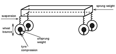
Effects of Unsprung Weight
The unsprung weight of a wheel controls a trade-off between a wheel's bump-following ability and its vibration isolation. Bumps and surface imperfections in the road cause tire compression--which induces a force on the unsprung weight. In time, the unsprung weight then responds to this force with movement of its own. The amount of movement is inversely proportional to the weight - a lighter wheel which readily moves in response to road bumps will have more grip when tracking over an imperfect road. For this reason, lighter wheels are often sought for high-performance applications. In contrast, a heavier wheel which moves less will not absorb as much vibration; the irregularities of the road surface will transfer to the cabin through the geometry of the suspension and hence ride quality is deteriorated.
Pneumatic or elastic tires help by providing some springing for most of the (otherwise) unsprung mass, but the damping that can be included in the tires is limited by considerations of fuel economy and overheating. The shock absorbers, if any, damp the spring motion also and must be less stiff than would optimally damp the wheel bounce. So the wheels execute some vibrations after each bump before coming to rest. On dirt roads and perhaps on some softly paved roads, these motions form small bumps, known as washboarding or "corduroy" because they resemble smaller versions of the bumps in roads made of logs. These cause sustained wheel bounce in subsequent vehicles, enlarging the bumps.
High unsprung weight also exacerbates wheel control under hard acceleration or braking. If the vehicle does not have adequate wheel location in the vertical plane (such as a rear-wheel drive car with Hotchkiss drive, a live axle supported by simple leaf springs), vertical forces exerted by acceleration or hard braking combined with high unsprung mass can lead to severe wheel hop, compromising traction and steering control.
Though this is usually not considered important, at least in the popular literature, there is a positive effect. High frequency road irregularities, such as the gravel in an asphalt or concrete road surface, are isolated from the body more completely because the tires and springs act as separate filter stages, with the unsprung weight tending to uncouple them. This can improve overall safety.
Unsprung Weight and Vehicle Design
Unsprung weight is largely a function of the design of a vehicle's suspension and the materials used in the construction of suspension components. Beam axle suspensions, in which wheels on opposite sides are connected as a rigid unit, generally have greater unsprung weight than independent suspension systems, in which the wheels are suspended and allowed to move separately. Heavy components such as the differential can be made part of the sprung weight by connecting them directly to the body (as in a de Dion tube rear suspension). Lightweight materials, such as aluminum, plastic, carbon fiber, and/or hollow components can provide further weight reductions at the expense of greater cost and/or fragility.
Inboard brakes make a big difference, but put more load on half axles and (constant velocity) universal joints and require space that may not be easily accommodated.
Thread Starter
legend behind the cowl
Joined: May 2006
Posts: 1,840
Likes: 0
In car handling, slip angle is the angle between a rolling wheel's actual direction of travel and the direction towards which it is pointing (i.e., the angle of the vector sum of wheel translational velocity vX and sideslip velocity vY). This slip angle results in a force perpendicular to the wheel's direction of travel -- the cornering force. This cornering force increases approximately linearly for the first few degrees of slip angle, then increases non-linearly to a maximum before beginning to decrease.
what this means in English for you and me... You turn into a corner, a slight amount of steering wheel input and the slip angle is near zero. so the car turns faster and faster with more steering wheel input. until eventually you exceed the slip angle your tires operate at then you begin to loose sideways (cornering) force.. in addition as your wheels near 45 degrees a good portion of that sideways cornering force becomes braking force pushing backward against the forward progress of the car. (this is often called "scrubbing speed" almost never a good thing when trying to set a lap time) and turns your momentum into heat and tire dust.
Just like when accelerating or braking the tire generates it's optimum force (Gription) when it's sliding but only a small percentage of it's overall movement.
This is where things start getting fun for the tuner since you can adjust the optimum slip angle with alignment, Tire loading (spring rate or sway bars)
A non-zero slip angle arises because of deformation in the tire carcass and tread. As the tire rotates, the friction between the contact patch and the road result in individual tread 'elements' (infinitely small sections of tread) remaining stationary with respect to the road. If a side-slip velocity u is introduced, the contact patch will be deformed. As a tread element enters the contact patch the friction between road and tire means that the tread element remains stationary, yet the tire continues to move laterally. This means that the tread element will be �deflected� sideways. In reality it is the tire/wheel that is being deflected away from the stationary tread element, but convention is for the co-ordinate system to be fixed around the wheel mid-plane.
As the tread element moves through the contact patch it will be deflected further from the wheel mid-plane: (and as you can guess a slick tire does not suffer this deformation)

This deflection gives rise to the slip angle, and to the cornering force.
Because the forces exerted on the wheels by the weight of the vehicle are not distributed equally, the slip angles of each tire will be different. The ratios between the slip angles will determine the vehicle's behavior in a given turn. If the ratio of front to rear slip angles is greater than 1:1, the vehicle will tend to understeer, while a ratio of less than 1:1 will produce oversteer. Actual instantaneous slip angles depend on many factors, including the condition of the road surface, but a vehicle's suspension can be designed to promote specific dynamic characteristics. A principal means of adjusting developed slip angles is to alter the relative roll couple (the rate at which weight transfers from the inside to the outside wheel in a turn) front to rear by varying the relative amount of front and rear lateral load transfer. This can be achieved by modifying the height of the Roll centers, or by adjusting roll stiffness, either through suspension changes or the addition of an anti-roll bar.
Now I can include all the math it takes to calculate these items, but for our purposes it's not required, just understand that whenever trying to make a suspension behave in a desired way the slip angle of the tires must always be taken into account. since exceeding the design of your tire will result in slower lap times and make your tuning much harder.
A good quote I was reminded about is "if your tire is growling you are close, if your tire is howling you've exceeded the slip angle" Back off a bit. we will also discuss later how driving style, by allowing the car to load up the tires properly, and using the dynamic weight shift of the vehicle. you will get increased performance out of the same exact car.


