


Bee R Rev limiter install *Guide*


Thread Starter
Nicolai
Joined: Oct 2005
Posts: 5,016
Likes: 0
 Bee R Rev limiter install *Guide*
I've had a hard time finding a easy to understand write-up on the Bee*R Rev Limiter / Power Builder, install. So decided to do a guide once i figured it out. Its very easy but if you dont know what wires to connect it to then it can be confusing. i fitted it in a 97 Kouki with s13 black top. more information can be found in the link below.
Reference and full wiring can be found here:
Bee-R Rev limiter fitting guide - Drifting forum - Driftworks
ECU:

First unplug your battery.
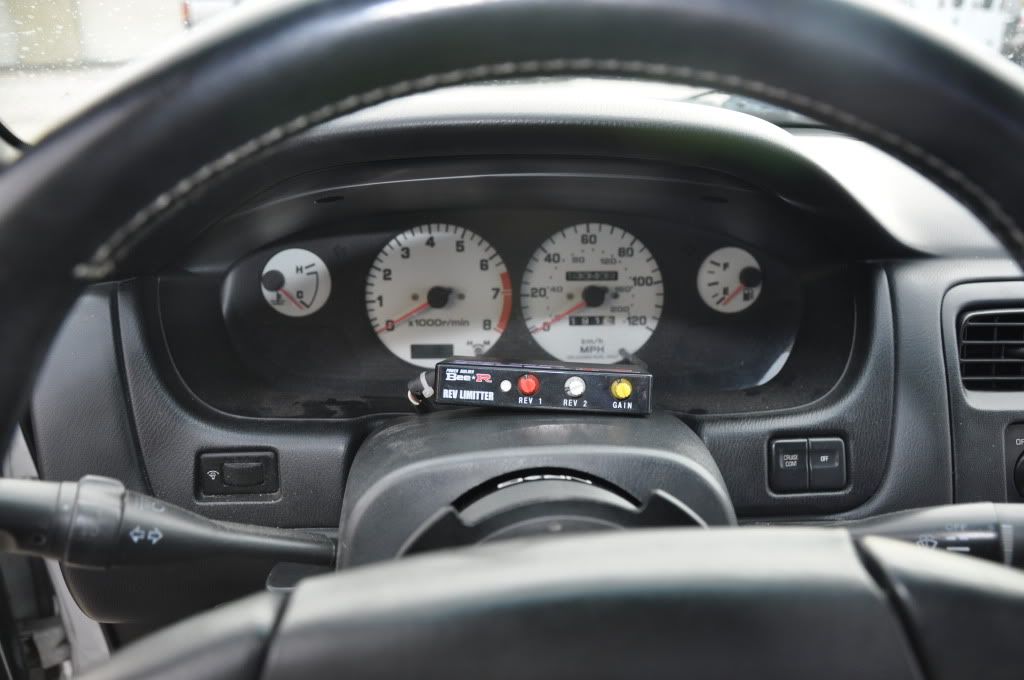
Then you want to find a mounting place for it. I put it on top of my steering column.
 .
.
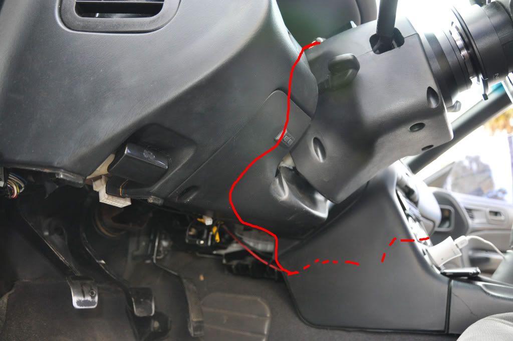
Route it to the ECU:
 .
.
 .
.
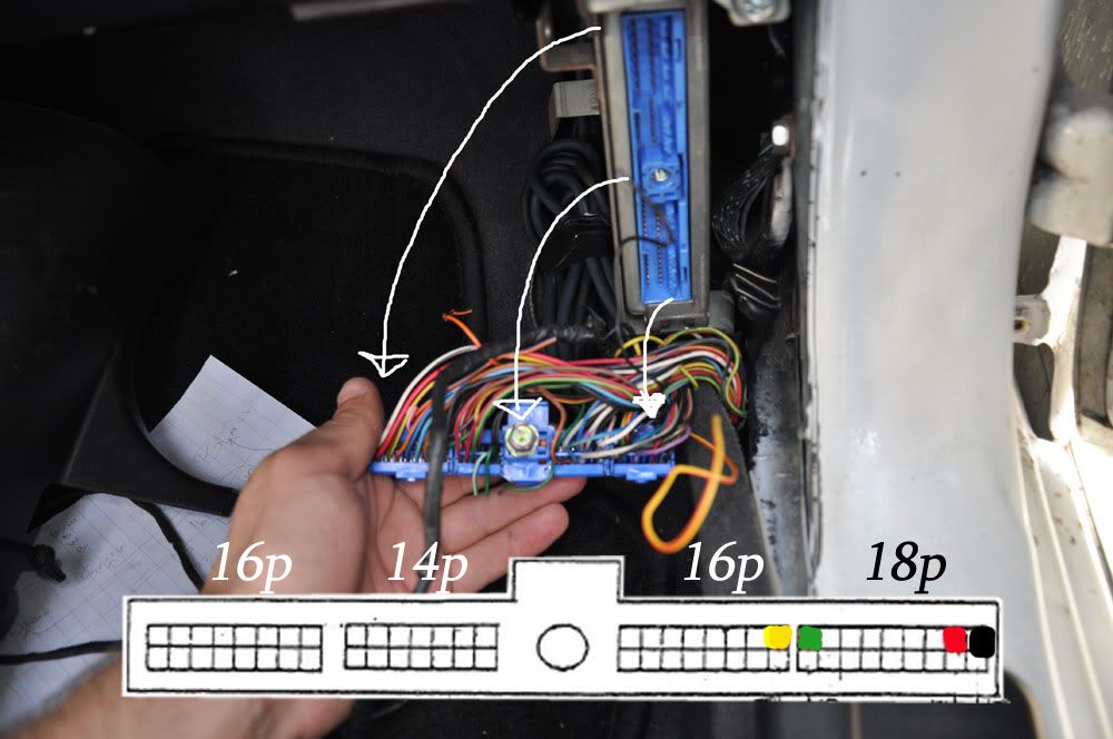
We color match the wires from the Bee-R to the ones in the diagram:
 .
.
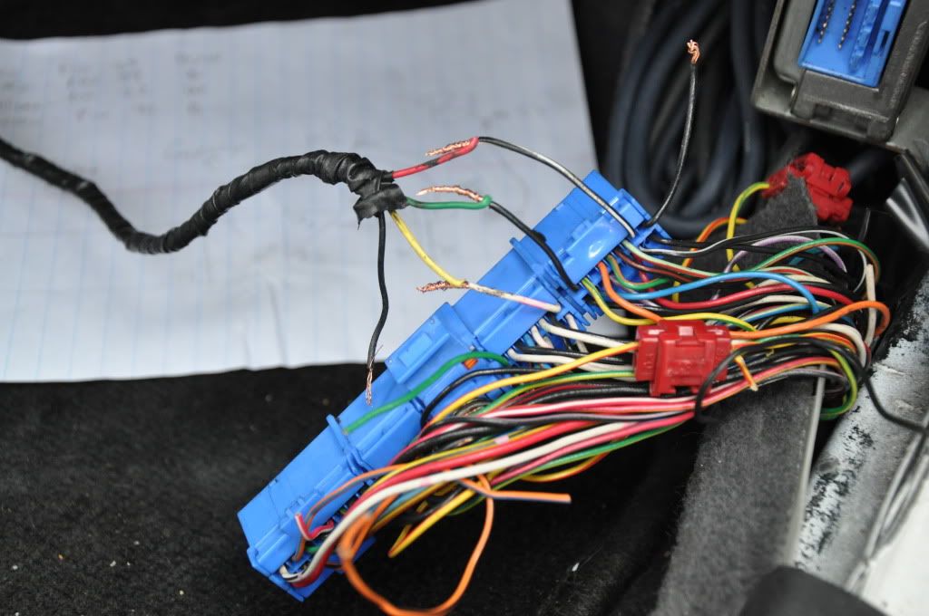
It will look something like this: Notice the last wires was not finished yet in the pic
 .
.
And dont forget to cover the connections with either shrink wrap or electrical tape. Once wrapped, connect the battery. Start the car up (Car will not start if Green and yellow wire on ECU are connected wrong way round). set the red knob on the left for the rev limiter.
settin 0 is 2500 RPM and settin F is 10,000 RPM
0 2500
1 3000
2 3500
3 4000
4 4500
5 5000
6 5500
7 6000
8 6500
9 7000
A 7500
B 8000
C 8500
D 9000
E 9500
F 10000
REV1 is the normal rev limit and REV2 is the limit when Handbrake/switch is engaged used
for launch control set up - (see in above link) i didnt care for it and my bee r was used and didnt have the white wire to connect to Ebrake.
GAIN (3rd knob) sets the frequency and length of cut. the lower the number the quicker the cut. e.g. 1 = bababababa F= BANG!!!......BANG!!!...... IF you set the GAIN to 0 the limiter wil not function.
This tutorial can be used for s14's with s13 sr. i used the N02 diagram from the link above. Depending on your ECU you might have to use the N01 diagram.
Hopefully it helps others.
Reference and full wiring can be found here:
Bee-R Rev limiter fitting guide - Drifting forum - Driftworks
ECU:
First unplug your battery.
Then you want to find a mounting place for it. I put it on top of my steering column.
.Route it to the ECU:
..We color match the wires from the Bee-R to the ones in the diagram:
.It will look something like this: Notice the last wires was not finished yet in the pic
.And dont forget to cover the connections with either shrink wrap or electrical tape. Once wrapped, connect the battery. Start the car up (Car will not start if Green and yellow wire on ECU are connected wrong way round). set the red knob on the left for the rev limiter.
settin 0 is 2500 RPM and settin F is 10,000 RPM
0 2500
1 3000
2 3500
3 4000
4 4500
5 5000
6 5500
7 6000
8 6500
9 7000
A 7500
B 8000
C 8500
D 9000
E 9500
F 10000
REV1 is the normal rev limit and REV2 is the limit when Handbrake/switch is engaged used
for launch control set up - (see in above link) i didnt care for it and my bee r was used and didnt have the white wire to connect to Ebrake.
GAIN (3rd knob) sets the frequency and length of cut. the lower the number the quicker the cut. e.g. 1 = bababababa F= BANG!!!......BANG!!!...... IF you set the GAIN to 0 the limiter wil not function.
This tutorial can be used for s14's with s13 sr. i used the N02 diagram from the link above. Depending on your ECU you might have to use the N01 diagram.
Hopefully it helps others.
__________________


 PBM fender roller for rent!!
PBM fender roller for rent!!
Last edited by robunicu; Dec 25, 2010 at 04:16 PM.

Registered User
Joined: Jan 2012
Posts: 1
Likes: 0
Is this correct? I don't think you cut the crank angle sensors..
This is my pin out:

PINS Description of use
1 Coil pack 1 output (via power transistor Unit)
2 Coil pack 2 output (via power transistor Unit)
3 Tachometer signal output
4 ECCS relay
5 Ignition pulse monitor (for trip comp ?)
6 Ignition Signal Ground
7 RX data (signal from Nissan Consult hand terminal)
8 Coil pack 3 output (via power transistor Unit)
9 Coil pack 4 output (via power transistor Unit)
10 -
11 -
12 A/T signal DT3 (autotrans gear select ?)
13 Ignition Signal Ground
14 CLK clock (timing signal) ?
15 TX data (signal to Nissan Consult hand terminal)
16 AFM Signal input (air flow meter)
17 AFM ground
18 Water temp sensor input
19 Oxygen Sensor input (O2)
20 TPS input (throttle position sensor)
21 Sensor ground
22 CAS 180deg signal (crank angle sensor)
23 CHK check (check start) ?
24 Monitor check lamp (Red) (fault code lamp output)
25 Exhaust over temp warning lamp output
26 Exhaust temp sensor input (behind the Cat)
27 Detonation sensor input (knock sensor)
28 TPS for A/T (kick down switch)
29 Sensor ground
30 CAS 180deg signal (crank angle sensor)
31 CAS 1deg signal (crank angle sensor)
32 Speed sensor input
33 -
34 START signal (from ignition switch)
35 A/T neutral switch input
36 IGN (ignition ON, from ignition switch)
37 TPS power output (power to throttle position sensor)
38 ECCS power
39 ECCS ground
40 CAS 1deg signal (crank angle sensor)
41 A/C on input (Air Con ON from A/C panel or climate control)
42 A/T signal DT1 (auto trans gear select ?)
43 Power steering switch (speed proportional control output)
44 A/T signal DT1 (auto trans gear select ?)
45 Ambient air temp sensor input
46 ECCS backup power
47 ECCS power
48 ECCS ground
101 Injector No 1 drive output
102 EAI control solenoid output (EGR valve control ?)
103 Injector No 3 drive output
104 Fuel pump relay output
105 Fuel pressure control module
106 A/C on output (Air Conditioner on relay signal)
107 Injector ground
108 Injector ground
109 Reverse electrical flow return circuit (alternator fail input ?)
110 Injector No 2 drive output
111 Turbo boost pressure control solenoid (over boost cut ?)
112 Injector No 4 drive output
113 AAC valve control (Auxiliary Air Control, idle speed control)
114 -
115 -
116 Injector ground
I cut 39 38 31 22, fitted up with the correct colours shown on the Bee-R wiring manual and your guide, and car sounded very sick, like it was about to die, and idle really rough..
Im guessing the instructions are wrong and don't cut the crank angle sensors.. and connect it to 6 Ignition Signal Ground and 1 Coil pack instead?
This is my pin out:
PINS Description of use
1 Coil pack 1 output (via power transistor Unit)
2 Coil pack 2 output (via power transistor Unit)
3 Tachometer signal output
4 ECCS relay
5 Ignition pulse monitor (for trip comp ?)
6 Ignition Signal Ground
7 RX data (signal from Nissan Consult hand terminal)
8 Coil pack 3 output (via power transistor Unit)
9 Coil pack 4 output (via power transistor Unit)
10 -
11 -
12 A/T signal DT3 (autotrans gear select ?)
13 Ignition Signal Ground
14 CLK clock (timing signal) ?
15 TX data (signal to Nissan Consult hand terminal)
16 AFM Signal input (air flow meter)
17 AFM ground
18 Water temp sensor input
19 Oxygen Sensor input (O2)
20 TPS input (throttle position sensor)
21 Sensor ground
22 CAS 180deg signal (crank angle sensor)
23 CHK check (check start) ?
24 Monitor check lamp (Red) (fault code lamp output)
25 Exhaust over temp warning lamp output
26 Exhaust temp sensor input (behind the Cat)
27 Detonation sensor input (knock sensor)
28 TPS for A/T (kick down switch)
29 Sensor ground
30 CAS 180deg signal (crank angle sensor)
31 CAS 1deg signal (crank angle sensor)
32 Speed sensor input
33 -
34 START signal (from ignition switch)
35 A/T neutral switch input
36 IGN (ignition ON, from ignition switch)
37 TPS power output (power to throttle position sensor)
38 ECCS power
39 ECCS ground
40 CAS 1deg signal (crank angle sensor)
41 A/C on input (Air Con ON from A/C panel or climate control)
42 A/T signal DT1 (auto trans gear select ?)
43 Power steering switch (speed proportional control output)
44 A/T signal DT1 (auto trans gear select ?)
45 Ambient air temp sensor input
46 ECCS backup power
47 ECCS power
48 ECCS ground
101 Injector No 1 drive output
102 EAI control solenoid output (EGR valve control ?)
103 Injector No 3 drive output
104 Fuel pump relay output
105 Fuel pressure control module
106 A/C on output (Air Conditioner on relay signal)
107 Injector ground
108 Injector ground
109 Reverse electrical flow return circuit (alternator fail input ?)
110 Injector No 2 drive output
111 Turbo boost pressure control solenoid (over boost cut ?)
112 Injector No 4 drive output
113 AAC valve control (Auxiliary Air Control, idle speed control)
114 -
115 -
116 Injector ground
I cut 39 38 31 22, fitted up with the correct colours shown on the Bee-R wiring manual and your guide, and car sounded very sick, like it was about to die, and idle really rough..
Im guessing the instructions are wrong and don't cut the crank angle sensors.. and connect it to 6 Ignition Signal Ground and 1 Coil pack instead?
Last edited by Mark2001311; Jan 17, 2012 at 10:31 AM.


