here you go Jason , got this from Honda tech- James

--> The four pairs wires coming off the fuel rail will have a common color of wire and one random color wire. If you look at the dsm clips, it will also have one common color wire and one random color wire.
The fuel rail has common yellow/black wire, and the dsm has common red wire. Take the common from each side, and solder them together for each clip. Then take the random wires and solder those together. order does not matter.
SOlder the wires together and use electrical tape to cover and protect the exposed wire.

-->Now that the clips are on, it's on to perparing the o-rings for installation. The tip of the injector on the dsm is wider in diameter then the stock injectors. This means you need to either buy larger o-ring injectors, or bore out the o-rings to fit.
Here is an side by side comparison of the diameter difference.

On obd1 Honda's, there is a "dead end" clip on the wiring harness in the right corner of the engine bay. (obd2 has this clip under the intake manifold). This clip has the electrical power running through it that goes to the injectors. It is right next to the clutch master cylinder.

--> Using a multimeter, check for conductivity between each clip and the end's of the "dead-end" connector. The idea is to find which wires actually are routed to the injector clips, so seeing if electricity can flow, you can guess-and-check and find out.
There are eight different wires going into the "dead-end" connector, all of which you must check to see if they are the winners! According to h-t, it could be random placed, so do not assume and follow my example. CHECK FOR YOURSELF TO MAKE SURE!

The red dots are showing which ones came out conductive for me. AGAIN, CHECK FOR YOURSELF TO MAKE SURE!
--> Once you found out which ones are conductive, move down 2-4 inches and cut the wire. This break in to wire is where you will have your resistor tie into the system. Strip both sides of the new striped wires.
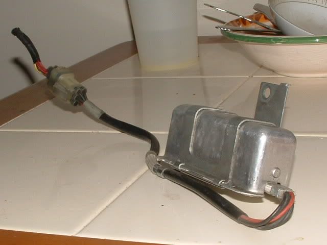
--> If you take a look at your resistor box, there should be 5 wires coming out of it. Four of them should be common color and one of them should be a different color. Strip all the ends if they are not already.

--> Next, Take the Single different color wire from the resistor box and solder it to all Four of the wires on the "dead-end" side. See diagram for better explaintion.


