Z-Fever:Anatomy of a Custom Intake Manifold (VQ35)

Registered User
Thread Starter

Join Date: Nov 2003
Posts: 45
Likes: 0
Received 0 Likes
on
0 Posts
I am Doug from Z-Fever. We build custom cars and do a lot of custom fabrication. We are currently building a VQ35DE powered 280ZX (old school but cool). We had to make a custom upper intake manifold to get the OEM hood to fit without hitting the engine. So, I figured I would do a tutorial of what it takes to make a custom intake manifold from start to finish.
I hope you find it interesting and educational.
Enjoy....
We start by scanning the stock gaskets where the lower plenum meets the intake manifold and the throttle body gaskets. Once we do that we digitize them to work with our design software. The images look like this:


Then we create those 2D image into 3D images:


Then from those images we create the program that will tell the machine how to cut the blocks of stainless into these shapes. This program details the speed the machine rotates each bit, what type of bit to use on each cut, in what order to make each cut, and more. The finished products look like this:


From here we create the image of what we expect the finished part will look like. We take the finished 3D images and fuse them together into a complete image. We also rotate and measure as we go making each piece fit so that we can get to the bolts on the intake flange. We map out exactly where each mandrel bent 2" tube has to be welded to the flange so that the clearances are accurate. This is what that looks like:


Then we make the intake plenum side wall where the mandrel bent tubes meet the intake. We make this ONLY after determining where the holes need to go in order to be able to get to the mounting points of the lower flange:

Then we put all the pieces together and cut out the 15"x15" piece of 16 gauge stainless that the intake plenum will be made from, the 4"x7" pieces that the front and back plenum walls will be made from, and we start welding.
Here is a pic of all the pieces before welding:

Here are the (6) - 2" 90 degree mandrels:

Here is the folded 15"x15" stainless section:

We start by welding the mandrels to the intake side wall (you will see that the folded intake section is attatched to this side wall at this point but only to keep the side wall from bending and contorting its shape while being welded on):


Then we weld the mandrels to the lower flange:


Then we cut off the sections of the mandrels that are sticking through the side wall of the plenum:

Then we fit the rounded plenum section to fit the side wall. Making sure that the clearance to the valve cover is accurate and also making sure that we increase velocity of airflow away from the throttle so that the cylinders furthest from the entry point get an equal amount of air as the one's closest to the entry point:


Then we weld the throttle body flange to the 3" stainless mandrel intake pipe:

Then we weld the 3" stainless mandrel pipe onto the intake plenum at the angle we need to make the clearance to the valve cover and the hood.... It looks a little something like this:
(BTW... you may notice the Z-Fever logo plate on the intake tube. We already made the cold air intake pipe with the air flow meter flange we made welded to it rather than using the stock black plastic air flow meter housing, looks a ton better in IMO)


This shot offers you a good look at the inside of the intake after it is all together.

By tomorrow morning (maybe 30 mins after we open) we will have this all closed up and the engine will be running. We will post dyno #'s after we get them to see if we have any actual realized gains.
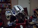
Here is the finished product, other than the fact that it still needs to be fully polished:


As always, I hope you appreciate our post.
I hope you find it interesting and educational.
Enjoy....
We start by scanning the stock gaskets where the lower plenum meets the intake manifold and the throttle body gaskets. Once we do that we digitize them to work with our design software. The images look like this:
Then we create those 2D image into 3D images:
Then from those images we create the program that will tell the machine how to cut the blocks of stainless into these shapes. This program details the speed the machine rotates each bit, what type of bit to use on each cut, in what order to make each cut, and more. The finished products look like this:
From here we create the image of what we expect the finished part will look like. We take the finished 3D images and fuse them together into a complete image. We also rotate and measure as we go making each piece fit so that we can get to the bolts on the intake flange. We map out exactly where each mandrel bent 2" tube has to be welded to the flange so that the clearances are accurate. This is what that looks like:
Then we make the intake plenum side wall where the mandrel bent tubes meet the intake. We make this ONLY after determining where the holes need to go in order to be able to get to the mounting points of the lower flange:
Then we put all the pieces together and cut out the 15"x15" piece of 16 gauge stainless that the intake plenum will be made from, the 4"x7" pieces that the front and back plenum walls will be made from, and we start welding.
Here is a pic of all the pieces before welding:
Here are the (6) - 2" 90 degree mandrels:
Here is the folded 15"x15" stainless section:
We start by welding the mandrels to the intake side wall (you will see that the folded intake section is attatched to this side wall at this point but only to keep the side wall from bending and contorting its shape while being welded on):
Then we weld the mandrels to the lower flange:
Then we cut off the sections of the mandrels that are sticking through the side wall of the plenum:
Then we fit the rounded plenum section to fit the side wall. Making sure that the clearance to the valve cover is accurate and also making sure that we increase velocity of airflow away from the throttle so that the cylinders furthest from the entry point get an equal amount of air as the one's closest to the entry point:
Then we weld the throttle body flange to the 3" stainless mandrel intake pipe:
Then we weld the 3" stainless mandrel pipe onto the intake plenum at the angle we need to make the clearance to the valve cover and the hood.... It looks a little something like this:
(BTW... you may notice the Z-Fever logo plate on the intake tube. We already made the cold air intake pipe with the air flow meter flange we made welded to it rather than using the stock black plastic air flow meter housing, looks a ton better in IMO)
This shot offers you a good look at the inside of the intake after it is all together.
By tomorrow morning (maybe 30 mins after we open) we will have this all closed up and the engine will be running. We will post dyno #'s after we get them to see if we have any actual realized gains.
Here is the finished product, other than the fact that it still needs to be fully polished:
As always, I hope you appreciate our post.
__________________
Z-Fever, Inc
4715 N Clark Ave
Tampa, FL 33614
813-877-7600
Doug Mitchell, Owner
Email: doug@zfever.com
www.zfever.com
www.VQ35swap.com


Z-Fever, Inc
4715 N Clark Ave
Tampa, FL 33614
813-877-7600
Doug Mitchell, Owner
Email: doug@zfever.com
www.zfever.com
www.VQ35swap.com
Last edited by Z Fever; 10-27-2011 at 08:10 AM.


Registered User
Join Date: May 2005
Posts: 3,191
Likes: 0
Received 0 Likes
on
0 Posts
nice Doug , three questions
do you have a cnc in house?
what program you use ? solid works?
why you used ss instead of aluminum?
do you have a cnc in house?
what program you use ? solid works?
why you used ss instead of aluminum?
__________________
 My shit still slow
618 whp 492 ft/lbs at 22 psi (Low Boost)on pump gas ,
stock block ,more power coming soon ,stay tuned
Tuned by Alpha @ Induction Performance
My shit still slow618 whp 492 ft/lbs at 22 psi (Low Boost)on pump gas ,
stock block ,more power coming soon ,stay tuned
Tuned by Alpha @ Induction Performance
2.4l 0f PuRe MaDn3ss
Join Date: Dec 2009
Posts: 709
Likes: 0
Received 0 Likes
on
0 Posts
Nyce
__________________
MaTt BuIlT-pRoJecT sPeCiAl K -c0mInG s0oN

StRiCkLy Mt
StricKlyMT https://www.tamparacing.com/forums/stricklymt/
Dc Crew Member#40
YaNk Kr3w#17
InDuCtIoN p3rFoRmAnCe
MaTt BuIlT-pRoJecT sPeCiAl K -c0mInG s0oN
StRiCkLy Mt
StricKlyMT https://www.tamparacing.com/forums/stricklymt/
Dc Crew Member#40
YaNk Kr3w#17
InDuCtIoN p3rFoRmAnCe
Registered User
Thread Starter
Join Date: Nov 2003
Posts: 45
Likes: 0
Received 0 Likes
on
0 Posts
Like I said in the post.. It is a little easier to weld. But also, it maintains its polish and looks awesome. We are using thermal gaskets to cut down on heat transfer.
__________________
Z-Fever, Inc
4715 N Clark Ave
Tampa, FL 33614
813-877-7600
Doug Mitchell, Owner
Email: doug@zfever.com
www.zfever.com
www.VQ35swap.com
Z-Fever, Inc
4715 N Clark Ave
Tampa, FL 33614
813-877-7600
Doug Mitchell, Owner
Email: doug@zfever.com
www.zfever.com
www.VQ35swap.com
Registered User
Thread Starter
Join Date: Nov 2003
Posts: 45
Likes: 0
Received 0 Likes
on
0 Posts
Here is the finished product installed along with video


And video of it running:
Z-Fever built VQ35 280ZX custom intake running.MOV - YouTube
And video of it running:
Z-Fever built VQ35 280ZX custom intake running.MOV - YouTube
__________________
Z-Fever, Inc
4715 N Clark Ave
Tampa, FL 33614
813-877-7600
Doug Mitchell, Owner
Email: doug@zfever.com
www.zfever.com
www.VQ35swap.com
Z-Fever, Inc
4715 N Clark Ave
Tampa, FL 33614
813-877-7600
Doug Mitchell, Owner
Email: doug@zfever.com
www.zfever.com
www.VQ35swap.com

Thread
Thread Starter
Forum
Replies
Last Post
2 to the 40 oz
For Sale/WTB Nissan
5
05-28-2010 07:56 PM
SpottedMango
Nissan/Infiniti Tech
24
08-04-2006 11:08 PM


